
1 Hardware Manual
This chapter introduces product overview, package contents, appearance, indicator and interface.
1.1 Overview
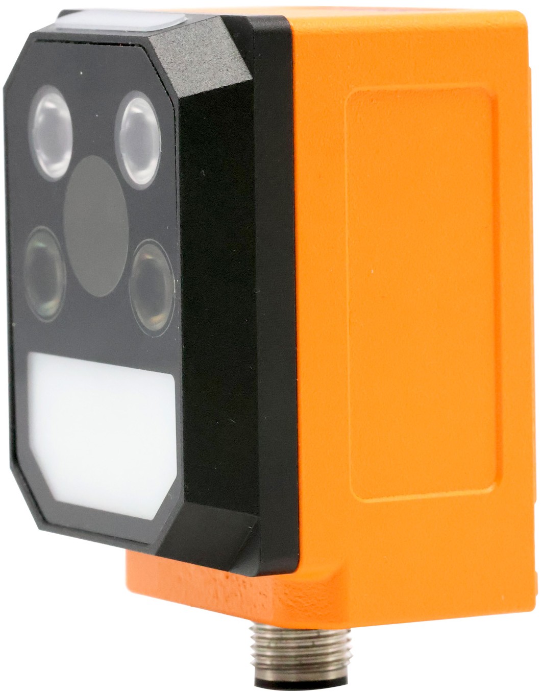
The ED-AIC1000 is an industrial smart camera based on Raspberry Pi CM0, equipped with a 1 GHz quad-core 64-bit Arm Cortex-A53 processor, integrated 512 MB SDRAM, and optional 8 GB / 16 GB eMMC storage. The device features a 1.3-megapixel global shutter image sensor with a capture rate up to 120 FPS, built-in motor auto-focus module, and modular three-zone independently controlled lighting. The case is made of orange industrial aluminum alloy, supporting flexible bracket mounting.
The ED-AIC1000 is equipped with a 12-Pin M12 aviation connector, integrating DC 24 V power input, 100M Ethernet, RS232, DO, and external trigger signals. It comes pre-installed with Raspberry Pi OS (Lite) 64-bit and supports industrial protocols such as Modbus TCP. The product offers three optional M12 fixed-focus lenses (6 mm, 8 mm, 12 mm), and can be upgraded with high-performance barcode reading algorithms for stable decoding of various 1D/2D codes, designed for demanding industrial automation vision inspection scenarios.
1.2 Package Contents
1 x ED-AIC1000 Unit
1.3 Appearance
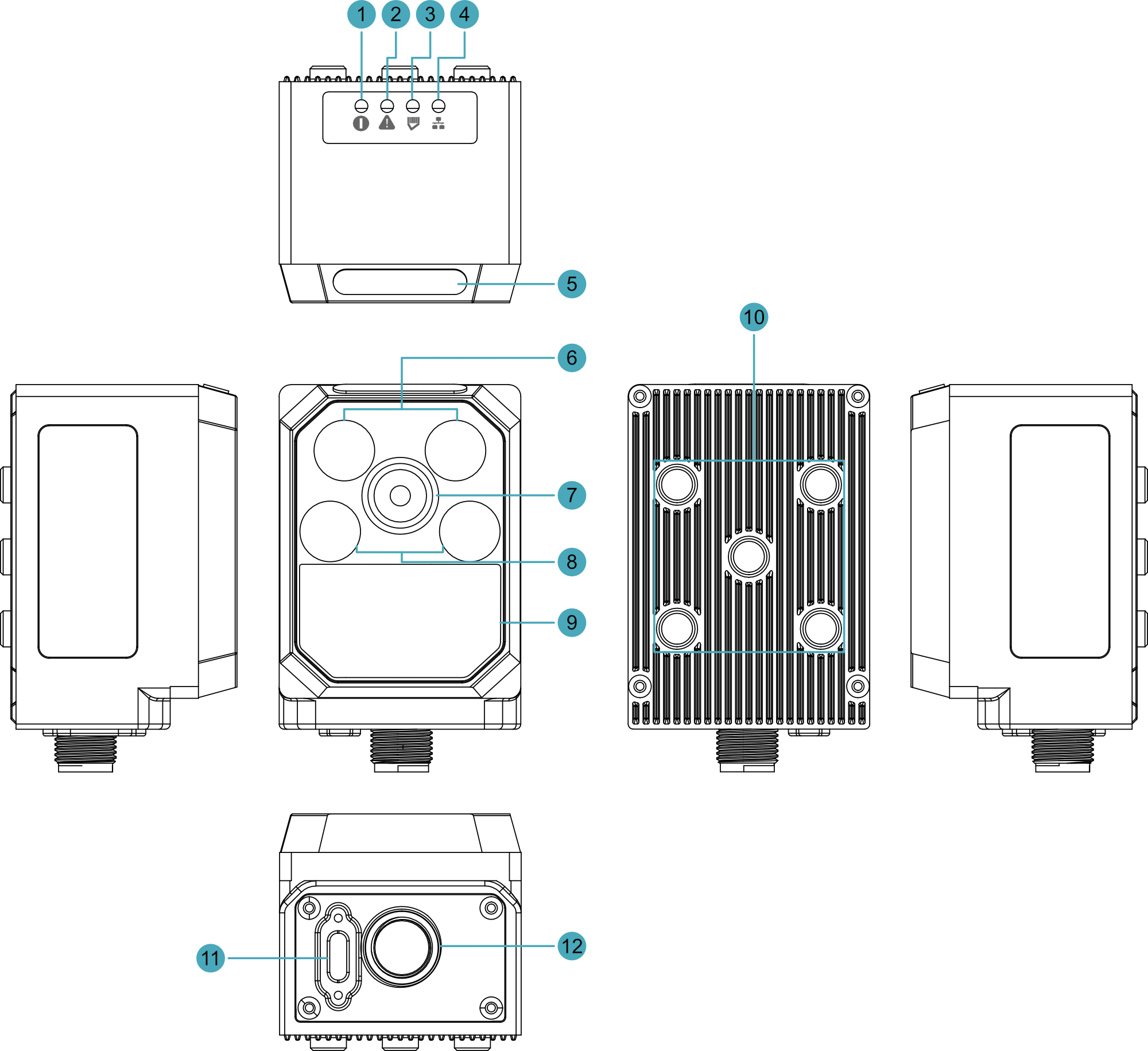
Introduces the functions and definitions of the product interfaces and indicators.
| NO. | Function Definition |
|---|---|
| 1 | 1 x Power indicator, which is used to check the power-on status of the device. |
| 2 | 1 x System fault indicator, which is used to check if a system fault occurs. |
| 3 | 1 x Working status indicator, which is used to check the working status of the device. |
| 4 | 1 x Network connection indicator, which is used to check the status of the network connection. |
| 5 | 1 x RGB light, configurable to red, green, blue, yellow, or white; user-customizable as needed |
| 6 | 1 x Light source (Top), used for supplementary lighting during device operation |
| 7 | 1 x M12 Lens, using to take photos. |
| 8 | 1 x Light source (Middle), used for supplementary lighting during device operation (with polarizer for enhanced lighting) |
| 9 | 1 x Light source (Bottom), used for supplementary lighting during device operation (white area at bottom, with diffuser plate for diffuse reflection lighting) |
| 10 | 5 x M4 screw holes for bracket mounting. |
| 11 | 1 x Type-C USB interface, used for eMMC programming |
| 12 | 1 x Power & I/O interface, including power interface, DO interface, RS232 serial port, and 100M Ethernet port, using a 12-Pin M12 aviation connector |
1.4 Indicator
Introduces the various states and meanings of the indicator lights on the ED-AIC1000 device.
| Indicator | Status | Description |
|---|---|---|
| Network connection indicator | Yellow blinking | Ethernet connected normally and data is being transmitted |
| Green solid | Ethernet not connected or no data transmission | |
| Off | Device not powered on | |
| Working status indicator | Green solid (controlled and set to ON via SDK) | The system is working normally |
| Red solid (controlled and set to ON via SDK) | System working status is abnormal | |
| Off | Default state (OFF) | |
| System fault indicator | Steady on | System fault detected |
| Off | No system fault | |
| Power indicator | Red solid | The device is powered on |
| Off | The device is not powered on |
Pin Definition
| Indicator | CM0 Pin |
|---|---|
| Power indicator | N/A |
| System fault indicator | GPIO19 |
| Working status indicator | GPIO20 (abnormal) GPIO21 (normal) |
| Network connection indicator | N/A |
1.5 Interface
Introduces the definitions and functions of each interface on the product.
1.5.1 Power & I/O Interface
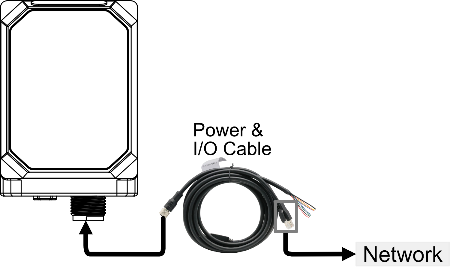
The ED-AIC1000 device includes one Power & I/O interface, using a 12-Pin M12 aviation connector. The Power & I/O interface contains 1 power input, 1 serial port, and 1 DO. The Power & I/O interface is used to connect the Power & I/O cable. One end of the cable is an M12 connector for connecting to the Camera; the other end consists of bare wires + RJ45 for connecting to power, DO, RS232, and network. The pin definitions of the M12 connector, bare wires, and RJ45 terminal are shown in the table below:
M12 Pin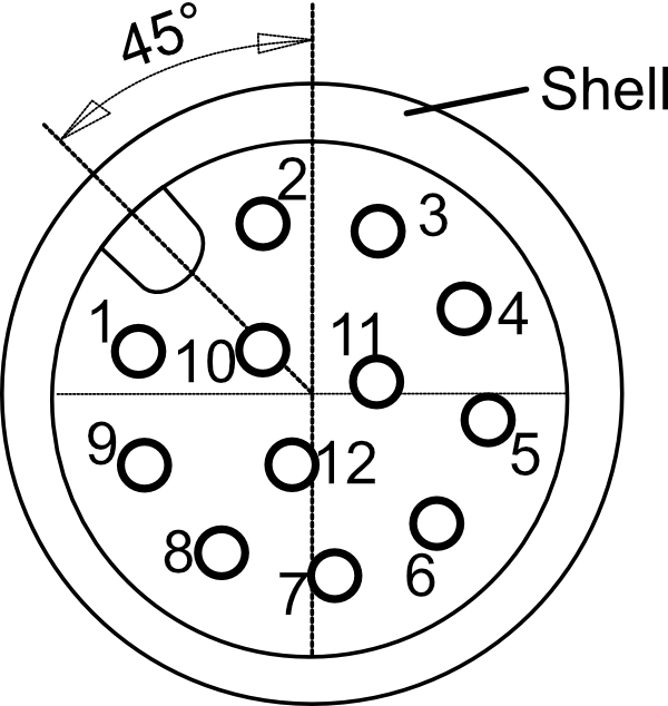 | Bare Wire Color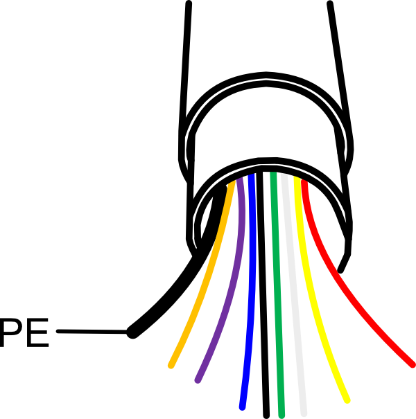 | Definition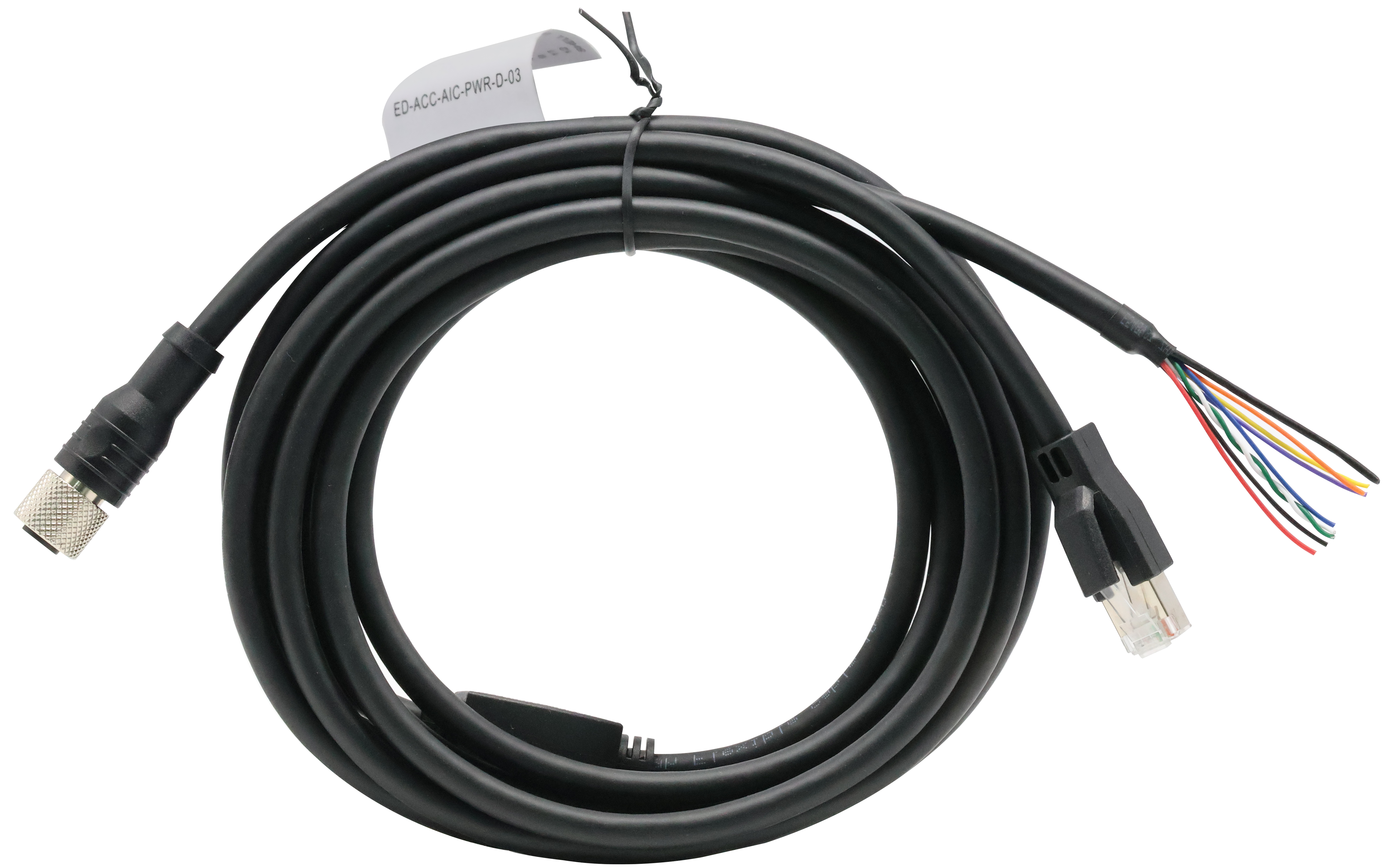 |
| 1 | RED | DC+ |
| 2 | Black | DC- |
| 3 | Orange | COMMON_IN |
| 5 | Blue | Trigger |
| 6 | Yellow | COMMON_OUT |
| 9 | Purple | DO_1 |
| 11 | White | RX232_TX |
| 12 | Green | RS232_RX |
| Shell | Black (Thick) | PE |
| Note: Pins 4, 7, 8, and 10 of the M12 connector are connected to the RJ45 terminal of the Power & I/O cable. | ||
The GPIO pins on the CM0 corresponding to the 1 DO channel are listed in the table below.
| Signal | CM0 Pin |
|---|---|
| DO1 | GPIO13 |
TIP
- The thickest black bare wire is PE.
- During installation, ensure that wire colors align with pin definitions and properly connect the PE to the ground terminal to guarantee safety and signal integrity.
- If there are unused bare wires during wiring, cut off the exposed metal ends or insulate them with electrical tape.
WARNING
Strictly follow the wiring instructions below to connect the power & I/O cable; incorrect wiring may result in device damage.
1.5.1.1 Power Connection
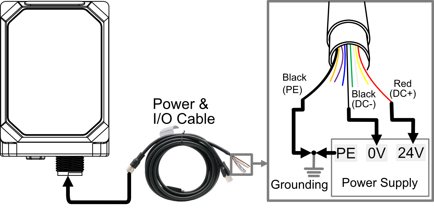
Among the bare wires of the Power & I/O cable, the red and black wires are used to connect to the positive and negative terminals of the external power supply respectively. The thick black wire is PE, used to connect to the ground wire.
WARNING
- The device power supply is DC 24 V (±10%). It is recommended to use a DC 24 V 1 A power adapter.
- When connecting the power cord, connect the PE from the bare wires and the PE from the external power supply to the ground wire, ensuring that PE is connected to earth ground.
1.5.1.2 DO Connection
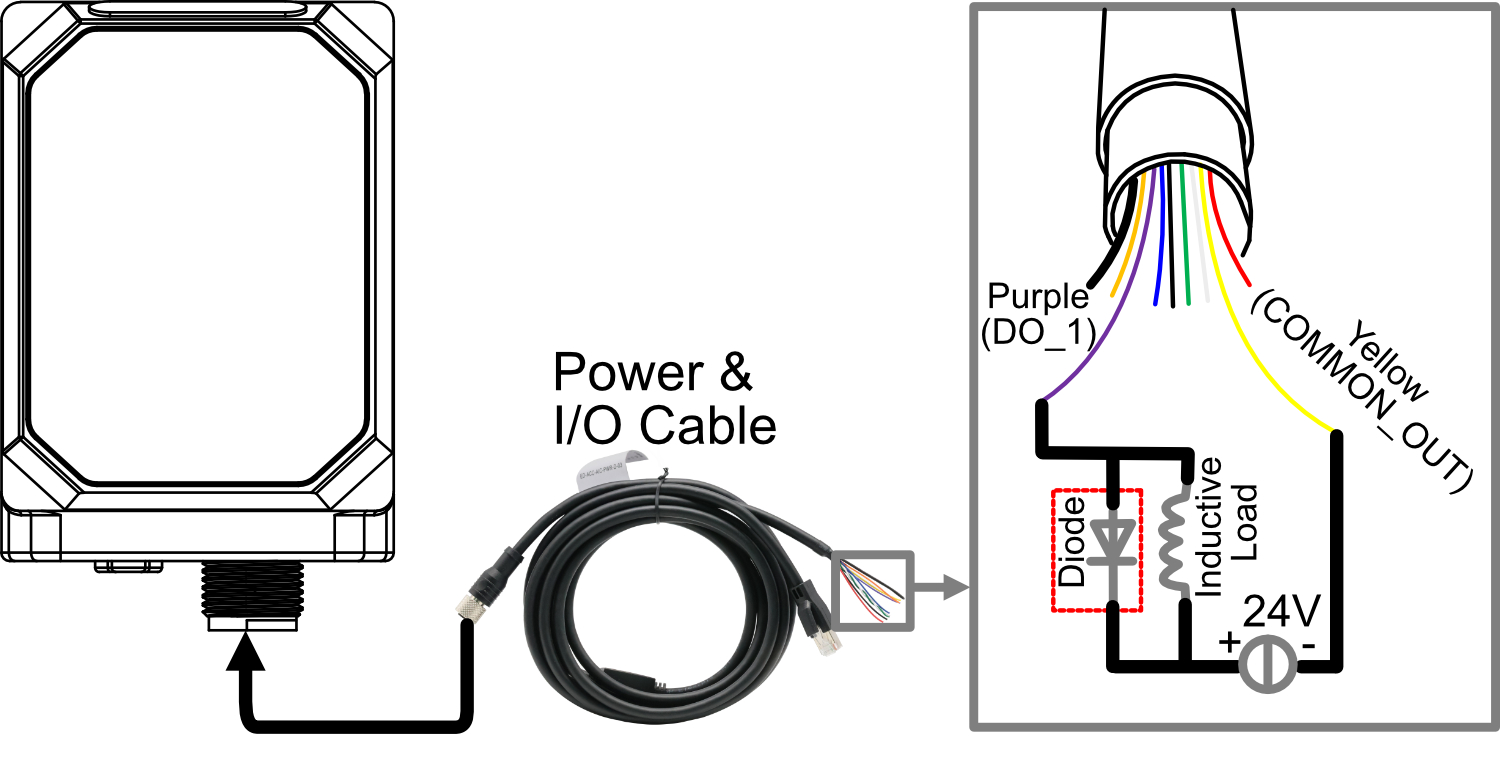
Among the bare wires of the Power & I/O cable, purple is for DO channel 1, and yellow is the common terminal for DO. The DO channel load capacity is 0.25 A. Supported load types include resistive loads, lamp loads, and inductive loads.

WARNING
- Do not connect the yellow wire (COMMON_OUT) to the positive terminal of 24 V.
- If the DO channel is connected to an inductive load externally, it is recommended to add a freewheeling diode in the circuit (as shown in the figure below) for protection. Select an appropriate freewheeling diode based on the specifications of the inductive load.
1.5.1.3 RS232 Connection
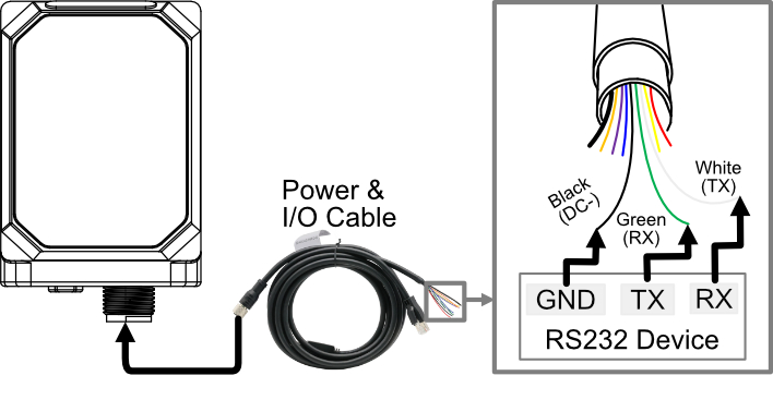
Among the bare wires of the Power & I/O cable, white is RS232_TX, and green is RS232_RX. This supports connection to RS232 devices.
1.5.1.4 Network Connection
The Power & I/O cable includes one RJ45 terminal (100M Ethernet port), supporting network connection.
1.5.2 USB-C interface
The ED-AIC1000 includes one USB Type-C interface, supporting to flash to eMMC by connecting to a PC.
1.6 Light source and lens
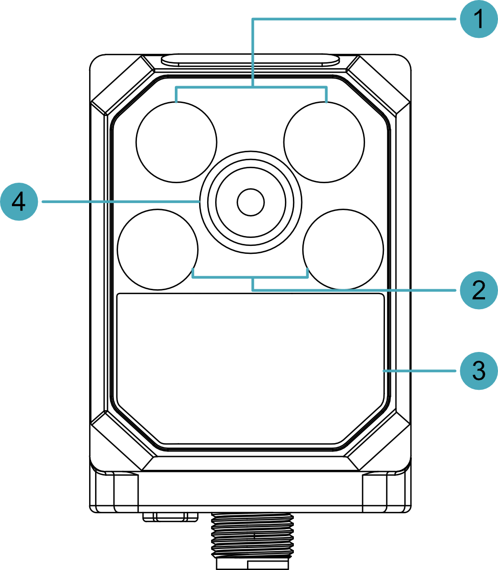
The ED-AIC1000 includes three light source sections and one lens.
| NO. | Description |
|---|---|
| 1 | Light source section 1 (Top, used for supplementary lighting during device operation); supports independent enable/disable. |
| 2 | Light source section 2 (Middle, used for supplementary lighting with polarizer during device operation); supports independent enable/disable. |
| 3 | Light source section 3 (Bottom, used for diffuse reflection supplementary lighting during device operation); supports independent enable/disable. |
| 4 | Lens, an M12 fixed-focal-length lens with a motor auto-focus module. |
1.7 RGB Light
The ED-AIC1000 includes one RGB side light. The light color can be set to red, green, blue, yellow, or white via software. The default state is OFF; users can customize it as needed.