
5 Configuring System
This chapter introduces how to configure system.
5.1 Finding Device IP
In some application scenarios, it is necessary to remotely log in or manage devices, so it is necessary to obtain the device IP.
5.1.1 View IP address At The Network Icon Of Desktop
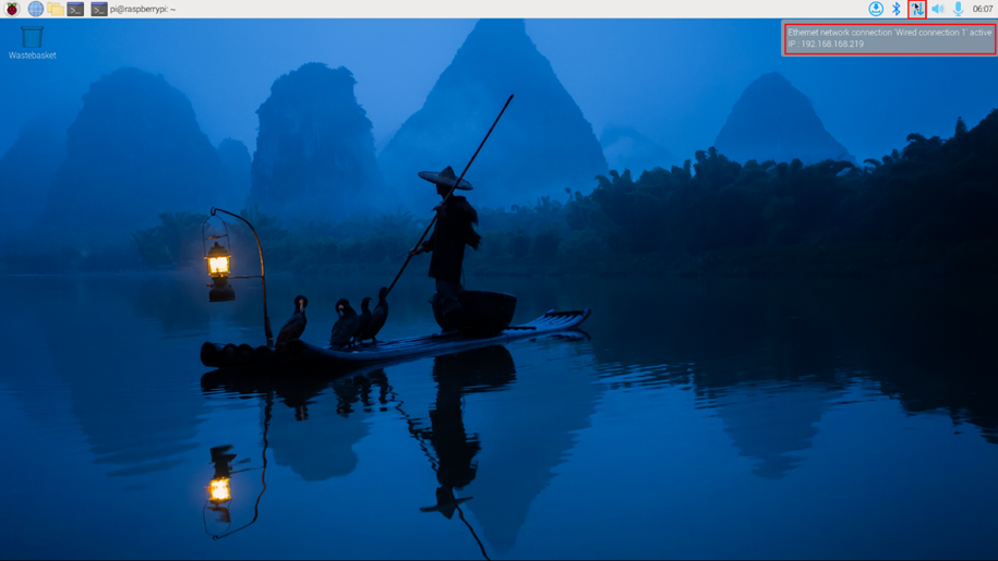
After the device starting normally and the display is connected, you can view the current device IP address at the Network icon.
TIP
Only supported by Desktop version system.
Preparation:
The device has been connected to the network through the router.
Steps:
Hover over the network icon in the system tray, and a tooltip will appear. This tooltip displays the name of the network you’re currently connected to and your IP address.
5.1.2 Hostname Command To Query
After the device starting normally and the display is connected, you can query the current device IP address by using hostname command.
Preparation:
The device has been connected to the network through the router.
Steps:
Run the following command in the command pane to obtain IP address.
hostname -I

5.1.3 Query IP by Using ifconfig Command
After the device is started normally and the display is connected, you can use the ifconfig command to view the current device IP.
Preparation:
The device has been connected to the network through the router.
Steps:
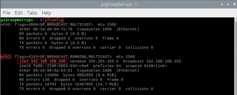
Run the following command in the command pane to view the detailed information of each port of the device, where the inet value in the eth1 interface is the device IP, as shown in the following figure.
ifconfig
WARNING
If the two Ethernet ports of device are all connected to Ethernet, the two IP addresses found are all device IP addresses.
5.1.4 Query IP by Using Network Manager CLI
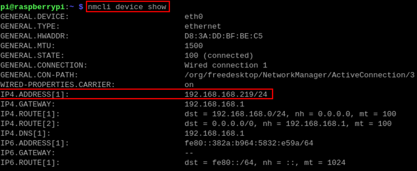
After the device is started normally and the display is connected, you can use the built-in Network Manager CLI (nmcli) to view details about your network.
Preparation:
The device has been connected to the network through the router.
Steps:
Run the following command in the command pane to view the detailed network information.
nmcli device show
5.1.5 Login Router To Query IP
When the device starts normally, you can log in to the router to check the current device IP.
Preparation:
- The device has been connected to the network through the router.
- The IP and network password of the router in the network have been obtained, and the IP address is 192.168.X.X.
Steps:
- Open a browser, Enter the router IP of the network where the device is located in the address bar: 192.168.x.x, and press Enter to enter the router login interface.
- According to the interface prompts, enter the network password and enter the router management interface.
- Find the IP address of device in the terminal device of the management interface.
5.1.6 Scan For Using NMAP Tool
When the device starts normally, you can use nmap tool to scan the IP under the current network to obtain the IP information of the device. Nmap supports Linux, macOS, Windows and other platforms.
Preparation:
- The device has been connected to the network through the router.
- The IP segment and mask of the router in the network have been obtained, for example, 192.168.X.X/24, where 24 is the subnet mask.
Steps:
For example, using nmap to scan the 192.168.3.0/24 subnet, you can use the following steps:
- Open the nmap tool and scan the hosts in the 192.168.X.X/24 network segment.
WARNING
The nmap tool operates differently in different operating systems, so please follow the actual interface or command prompts.
- According to the scanned results, get the device IP.
5.2 Remote Login
There are many remote login methods, and users can choose according to their actual needs. This chapter only introduces SSH and VNC.
5.2.1 Connect To The Device Via SSH
After the device starts normally, you can choose to connect to the device remotely through SSH to configure or debug it. The tools for remote login are selected by users themselves, and the following is an example of logging in through MobaXterm.
Preparation:
- The
MobaXtermtool has been installed on the PC. - The device has been connected to the network through the router.
- IP address of the device has been get.
Steps:
- Open
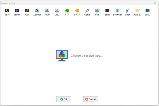
MobaXterm, click , and open the window for creating connection, as shown in the figure below.
- Click
 in the upper left corner to open the SSH connection interface.
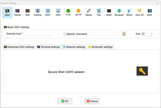
- After entering the IP address of the obtained device, click "OK".
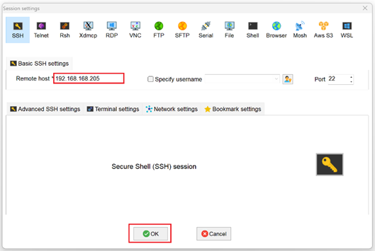
- Click "Accept" in the pop-up prompt box to enter the system login interface.
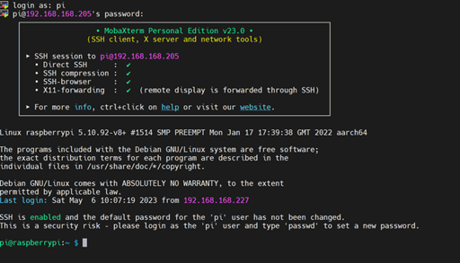
- Enter the username and password according to the prompt, and enter the system after logging in.
TIP
Default username is pi, Default password is raspberry.
5.2.2 Connect To The Device Desktop Through VNC
After the device starts normally, you can choose to connect to the device remotely through VNC to configure or debug it.
Preparation:
- The
RealVNC Viewertool has been installed on PC. - The device has been connected to the network through the router.
- IP address of the device has been get.
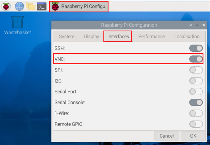
- The VNC function in the system has been turned on, as shown in the following figure.
Steps:
- Open
RealVNC Viewerand select "New connection…" in the File in the menu bar to open the window for creating a connection, as shown in the following figure.
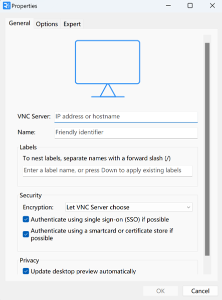
- After entering the IP address of device, click "OK".
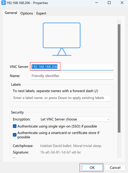
- Enter the username and password in the Authentication prompt box that pops up.
TIP
Default username is pi, Default password is raspberry.
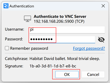
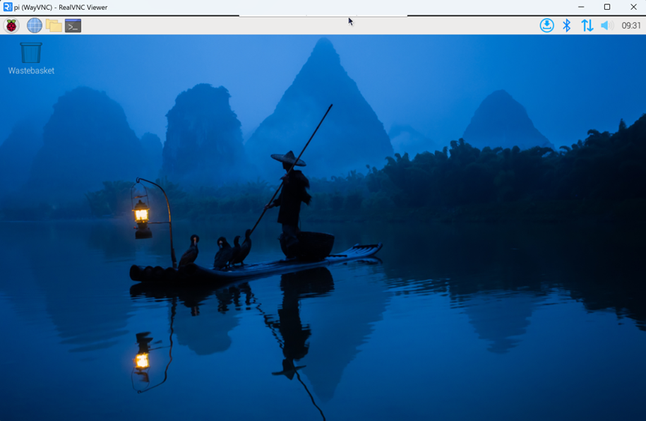
- Select "OK" to log in and connect to the remote desktop.
5.3 Configuring Storage Devices
You can connect your external SSD or USB disk to the corresponding port on the device and mount the file system to access the data stored on it. When the device is turned off, it is necessary to unmount the storage device so that it can be safely pulled out.
The connectable storage devices of device include USB storage devices and SSD. This chapter introduces how to configure the mounting and unmounting of storage devices.
5.3.1 Mounting a Storage Device
If the Lite version of the operating system is used (the Desktop version of the system supports automatic mounting), after the storage device is connected to the corresponding port on the device, it is necessary to mount the storage device in a specific folder location through configuration, usually in the /mnt folder, such as /mnt/mydisk.
TIP
The /mnt folder must be empty.
Preparation:
The storage device is ready to be mounted.
Steps:
- Connect the storage device to be mounted to the corresponding port on the device (USB storage device is inserted into USB port).
- Run the following command to view all disk partitions on the device.
sudo lsblk -o UUID,NAME,FSTYPE,SIZE,MOUNTPOINT,LABEL,MODEL
After running the command, the information displayed is as follows:

UUID, NAME, FSTYPE, SIZE, MOUNTPOINT, LABEL and MODEL are disk parameters that need to be listed.
The types of MOUNTPOINT are
/and/boot.The storage device whose LABEL is
ADMESYis the inserted USB storage device, and the corresponding disk name is sda1.FSTYPE indicates the file system type contained.
If the file system type of the inserted storage device is exFAT, please run the following commands to install the exFAT driver.
sudo apt update
sudo apt install exfat-fuse
- If the file system type of the inserted storage device is NTFS (only read permission is supported), you can install ntfs-3g driver to realize write permission. Run the following commands to install ntfs-3g drivers.
sudo apt update
sudo apt install ntfs-3g
- Run the following command to get the location of the disk partition.
sudo blkid
After running the command, the following information is displayed, which the disk partition of the connected storage device is displayed as /dev/sda1.

- Create a target folder as the mount point of the storage device. Assuming that the mount name is
mydiskand the directory to be mounted is/mnt, the command to be executed is as follows:
sudo mkdir /mnt/mydisk
- Mount the storage device at the created mount point, and execute the following command:
sudo mount /dev/sda1 /mnt/mydisk
- Verify the success of mounting the storage device by executing the following command.
ls /mnt/mydisk
- After executing the command, if the displayed information lists all files in the storage device, it means that the mount is successful.
- After executing the command, if the displayed information does not list the contents of related files, it means that the mount is failed.
5.3.2 Unmount The Storage Device
When the device is turned off, it is necessary to manually unmount the storage device so that it can be pulled out safely.
WARNING
Both Lite and Desktop versions of the system need to manually unmount the storage device.
Preparation:
The storage device has been successfully mounted.
Steps:
If /mnt is the mounted directory and mydisk is the name of the mount point, you can execute the following command to complete the unmounting.
sudo umount /mnt/mydisk
- After executing the command, if no error message is displayed, it means that the unmounting has been completed and the storage device can be completely pulled out.
- After executing the command, if an error message is displayed, it means that the unmounting is failed.
5.3.3 Set The Storage Device To Mount Automatically
If you are using the Lite version of operating system, you can automatically mount it by modifying the fstab settings.
Preparation:
The storage device to be mounted has been connected to the corresponding port on the device.
Steps:
- Execute the following command to view all disk partitions on the device and get the file system type of the storage device to be mounted, as “vfat” shown in the figure below.
sudo lsblk -o UUID,NAME,FSTYPE,SIZE,MOUNTPOINT,LABEL,MODEL

- Execute the following command to obtain the UUID of the storage device to be mounted, such as "7C9E-4F13" in the figure below.
sudo blkid

- Execute the following command to open the fstab file.
sudo nano /etc/fstab
- Add the following to the fstab file.
UUID=7C9E-4F13 /mnt/mydisk vfat defaults,auto,users,rw,nofail 0 0
- The value of UUID is the value found in Step 2 above.
/mntis the directory to be mounted, andmydiskis the name of the mount point.- Vfat is the file system type queried in step 1.
- If the type of file system is FAT or NTFS, the added content is "
UUID = 7C9E-4F13 /mnt/mydisk vfat defaults,auto,users,rw,no fail umask = 000 0 0",which will allow all users to "read/write" access to each file on the storage device.
WARNING
More information about the fstab command can be viewed by executing the man fstab command.
- Use
Ctrl+Xto save the file and exit edit mode.
5.4 Configuring Ethernet IP
The IP address is automatically obtained by default. If you need to reconfigure the IP, you can configure it through NetworkManager and dhcpcd.
5.4.1 Configure IP By Using The NetworkManager Tool
The operating systems of Desktop and Lite have enabled NetworkManager by default, which can be directly configured by using NetworkManager.
5.4.1.1 Raspberry Pi OS (Desktop)
In the Desktop version of the operating system, it is recommended to use the graphical NetworkManager tool to configure IP.
WARNING
The Desktop version of the operating system has the NetworkManager graphical tool installed by default.
Preparation:
Wi-Fi is enabled.
Steps:
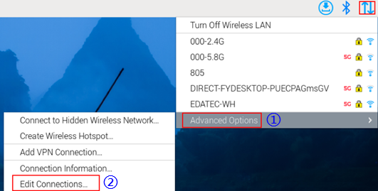
- Left-click the
 icon in the upper right corner of the desktop and select “Advanced Options” → “Edit Connections” in the pop-up menu.
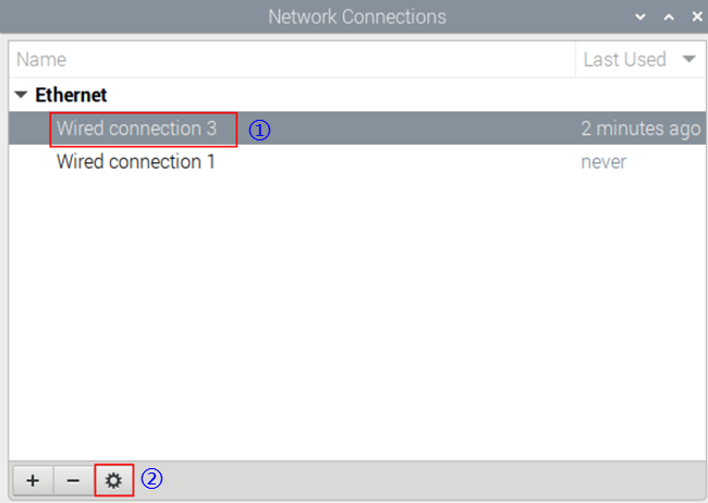
- In the pop-up "Network Connections" pane, select the connection name to be modified, and then click the Settings button below.
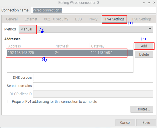
- In the pop-up "Editing Wired connection" pane, select the "IPv4 Settings" page, and then set the IP address as required.
- If you want to set the IP as a static IP, set the "Method" as "Manual", add an entry in Addresses and enter the corresponding IP address information.
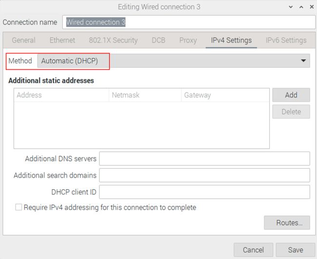
- If you want to set the IP to automatic mode, you only need to set the "Method" as "Automatic(DHCP) ".
- Click "save" to return to "Network Connections" pane and close the page.
- Execute the
sudo rebootcommand to restart the device.
5.4.1.2 Raspberry Pi OS (Lite)
In the Lite version of operating system, it is recommended to use the command to configure IP.
Preparation:
NetworkManager is enabled.
Steps:
- Set a static IP address
- Get the assigned IP address, subnet mask and gateway address, for example, the IP address is 192.168.1.101/24 and the gateway IP is 192.168.1.1.
- Obtain the connection name to be modified, for example
e167c45f-efed-3f8d-89a5-f2430f92fae8. In the command pane, run the following command to query the connection name.
nmcli c

- Execute the following command to set the IP address to the obtained IP address.
sudo nmcli connection modify e167c45f-efed-3f8d-89a5-f2430f92fae8 ipv4.addresses 192.168.1.101/24 ipv4.method manual
- Execute the following command to set the gateway IP to the obtained gateway IP.
sudo nmcli connection modify e167c45f-efed-3f8d-89a5-f2430f92fae8 ipv4.gateway 192.168.1.1
- Set the IP to automatic mode
- Obtain the connection name to be modified, for example
e167c45f-efed-3f8d-89a5-f2430f92fae8. In the command pane, run the following command to query the connection name.
nmcli c

- Execute the following command to set the way of obtaining IP address to automatic mode.
sudo nmcli connection modify e167c45f-efed-3f8d-89a5-f2430f92fae8 ipv4.method auto
5.4.2 Configure IP By Using The dhcpcd Tool
Since NetworkManager is enabled on the Desktop and Lite of operating systems by default. If you need to switch to using the dhcpcd tool for configuration, you need to stop and disable the NetworkManager service and enable the dhcpcd service before configuration.
Steps:
- Execute the following command to stop the NetworkManager service.
sudo systemctl stop NetworkManager
- Execute the following command to disable the NetworkManager service.
sudo systemctl disable NetworkManager
- Execute the following command to enable the dhcpcd service.
sudo systemctl enable dhcpcd`
- Execute the following command to restart the device.
sudo reboot
- Execute the following command to open the
/etc/dhcpcd.conffile.
sudo nano /etc/dhcpcd.conf
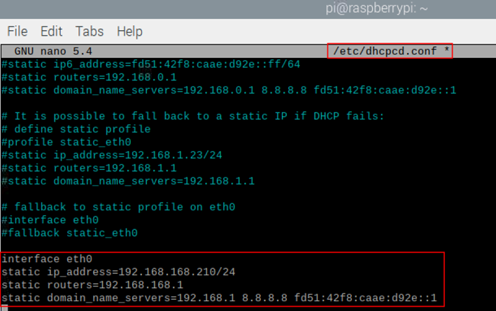
- Add the following content at the end of the
/etc/dhcpcd.conffile.
   interface eth0
   static ip_address=192.168.168.210/24
   static routers=192.168.168.1
   static domain_name_servers=192.168.168.1 8.8.8.8 fd51:42f8:caae:d92e::1
eth0is the Ethernet port of the IP to be configured;192.168.0.10/24indicates the IP address and subnet mask to be configured;192.168.0.1indicates the gateway IP to be configured;8.8.8.8represents the DNS server address, which should be configured according to the actual needs.fd51:42f8:caae:d92e::1indicates the IPV6 address, which should be configured according to the actual needs.
- Use
Ctrl+Sto save the file, then enterCtrl+Xto exit edit mode. - Execute the following command to reboot the device.
sudo reboot
5.5 Configuring Wi-Fi (Optional)
User can choose the device with Wi-Fi version, which needs to be configured before using Wi-Fi function.
The Wi-Fi feature is enabled by default, with the WLAN country code preset to "CN China". Before connecting to a Wi-Fi network, you need to modify the WLAN country code to match your location's regulatory requirements.
5.5.1 Set WLAN Country Code
The default WLAN country code is set to "CN China". Please configure an appropriate WLAN country code before connecting to Wi-Fi.
5.5.1.1 Raspberry Pi OS (Desktop)
In the Desktop version of the operating system, you can use the desktop menu to set WLAN country code.
Steps:
- Left-click the icon
 in the top-left corner of the desktop and select "Preferences"→"Raspberry Pi Configuration" in the menu.

- In the
Raspberry Pi Configuration interface, select "Localisation".
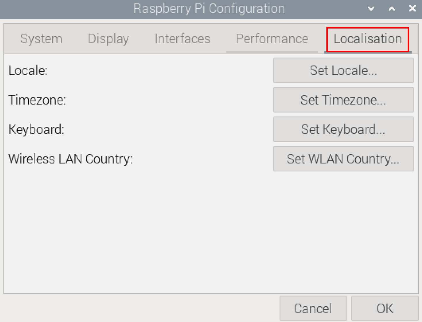
- Click "Set WLAN Country...", Set the value of Country in the pop-up "Wireless LAN Country" pane, and select it to match your location's regulatory requirements.
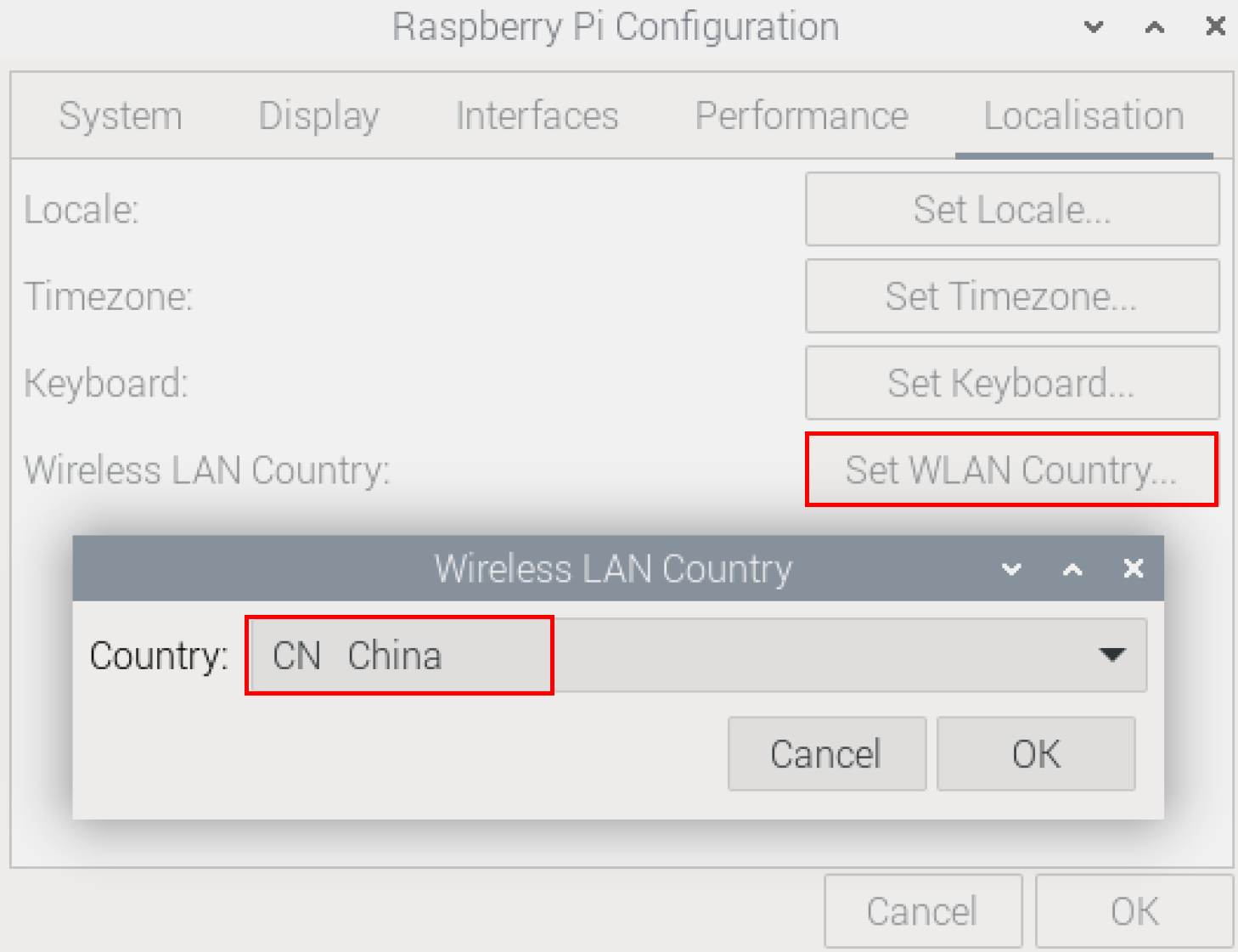
- Select "OK" to complete the setting.
5.5.1.2 Raspberry Pi OS (Lite)
In the Lite version of the operating system, you can use the command line to set WLAN country code.
Setps:
- Open the command terminal pane and execute the following command to open the
Raspberry Pi Software Configuration Tool (raspi-config)interface.
sudo raspi-config
- Choose "5 Localisation Options" and press "Enter".
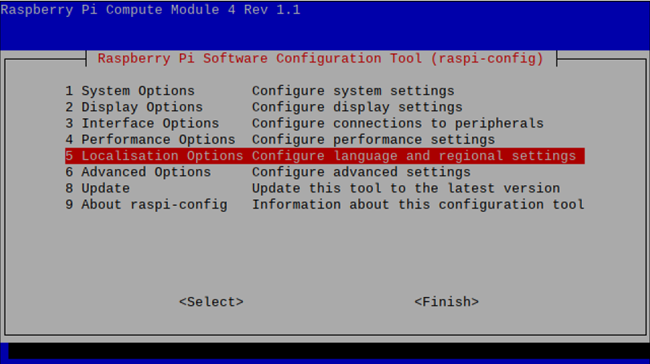
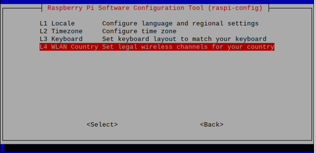
- Select "L4 WLAN Country" and press "Enter".
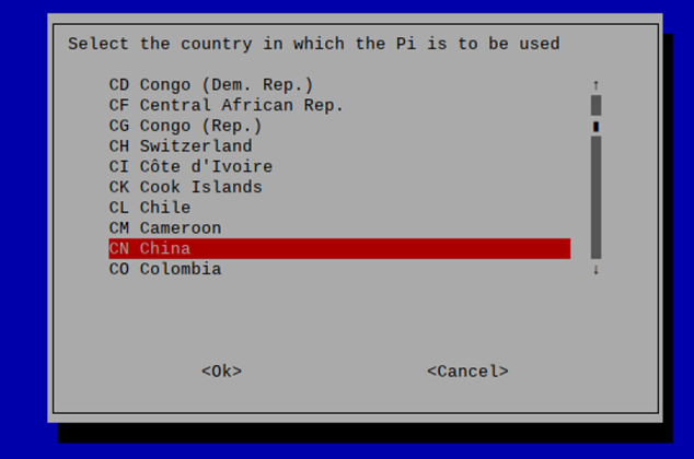
- Select a country code to match your location's regulatory requirements and press "Enter".
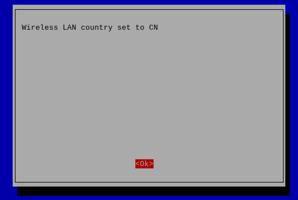
- Press "Enter" in
Wireless LAN country set to CNinterface.
- In the main interface of the pane, select "Finish" and press Enter to complete the setting and return to the command line.
5.5.2 Use The NetworkManager Tool To Configure Wi-Fi Connections
The operating systems of Desktop and Lite have enabled NetworkManager by default, which can be directly configured by using NetworkManager.
5.5.2.1 Raspberry Pi OS (Desktop)
In the Desktop version of the operating system, you can connect to Wi-Fi through the desktop icon.
Preparation:
Wi-Fi function is enabled.
Steps:
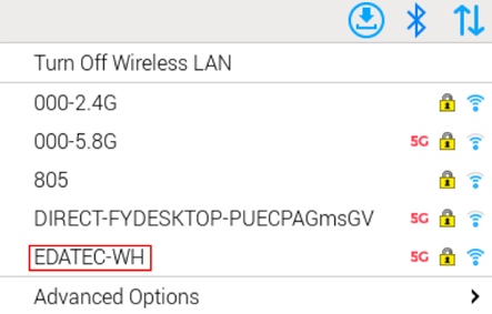
- Left-click the icon in the upper right corner of the desktop, select the Wi-Fi name and click it in the pop-up Wi-Fi list.
- Input the Wi-Fi Password in the pop-up
Wi-Fi Network Authentication Requiredpane.
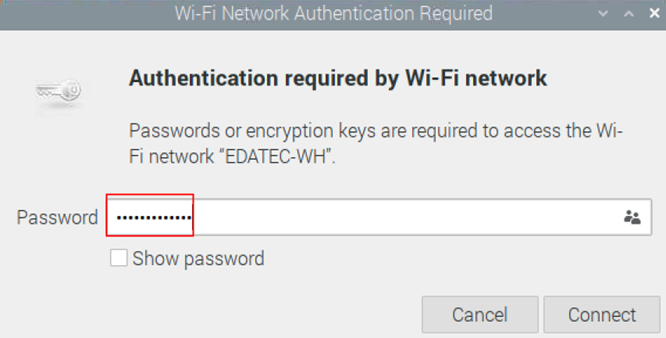
- Click "Connect" to connect to the network. After the connection is completed, you can click icon to view Wi-Fi information.
5.5.2.2 Raspberry Pi OS (Lite)
In the Lite version of the operating system, it is supported to configure Wi-Fi through the command line.
Preparation:
- Wi-Fi function is enabled.
- The Wi-Fi name and password that can be connected are prepared, for example, the Wi-Fi name is
SSIDand the password ispassword.
Steps:
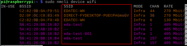
- Open the terminal and execute the following command to scan the list of connectable Wi-Fi name.
sudo nmcli device wifi
- Execute the following command to connect the Wi-Fi.
sudo nmcli device wifi connect SSID password password
Where SSID is the name of the Wi-Fi and the second password is the password of the Wi-Fi.
- Execute the following command to set up automatic Wi-Fi connection.
sudo nmcli connection modify SSID connection.autoconnect yes
- Where
SSIDis the name of the Wi-Fi.
5.5.3 Configure Wi-Fi Connection By Using raspi-config Tool
In both Desktop and Lite versions of the operating system, you can connect to Wi-Fi through the raspi-config tool.
Preparation:
- Wi-Fi function is enabled.
- The Wi-Fi name and password that can be connected are prepared, for example, the Wi-Fi name is
EDATEC-WHand the password ispassword.
Steps:
- Open the terminal and execute the following command to open the
Raspberry Pi Software Configuration Tool (raspi-config)interface.
sudo raspi-config
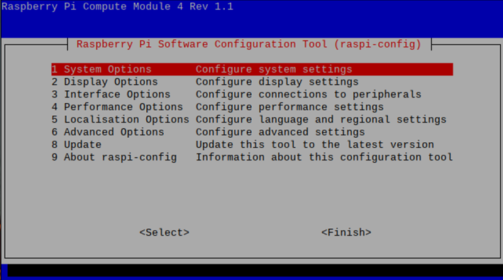
- Select "1 System Options" and press "Enter", and then select "S1 Wireless LAN" in the interface.
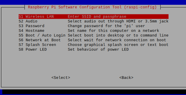
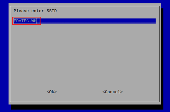
- Press "Enter", then input the Wi-Fi name in the
Please enter SSIDinterface.
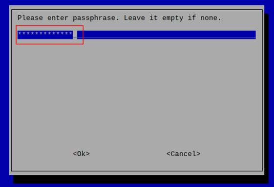
- Press "Enter", then input the Wi-Fi password in the
Please enter passphrase. Leave it empty if noneinterface.
- Press "Enter" to connect Wi-Fi. When the Wi-Fi is connected successfully, select "Finish" and press "Enter" to complete the setting and return to the command line window.
5.6 Configuring Bluetooth (Optional)
User can choose the device with Bluetooth version, and the Bluetooth function is enabled by default, You need to finish related configurations such as adding devices, scanning devices and device pairing before using Bluetooth.
5.6.1 Raspberry Pi OS (Desktop)
In the Desktop version of the operating system, you can use the desktop icon to configure Bluetooth.
Steps:
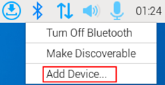
- Left-click the icon
 in the upper right corner of the desktop and select “Add Device” in the pop-up menu.
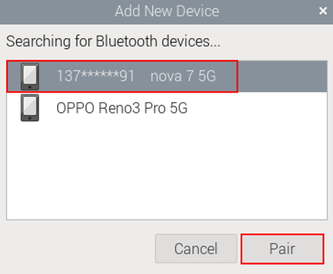
- In the pop-up "Add New Device" pane, view the scanned Bluetooth devices. Then you can select a Bluetooth device, and click “Pair” to start pairing.
- Select “OK” in the pop-up prompt box to confirm the pairing request.

TIP
You need confirm the pairing request on connected Bluetooth device, otherwise the pairing will fail.
- After successful Bluetooth pairing, click “OK” in the pop-up prompt to close the page.
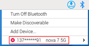
- Left-click the icon in the upper right corner of the desktop to view the connected Bluetooth device.
5.6.2 Raspberry Pi OS (Lite)
In the Lite version of the operating system, you can use the command line to configure Bluetooth.
5.6.2.1 Basic Configuration Command
| Command | Function Description |
|---|---|
| bluetoothctl scan on | Enable Bluetooth scanning |
| bluetoothctl scan off | Disable Bluetooth scanning |
| bluetoothctl discoverable on | Enable Bluetooth discovery (which can be discovered by the other party) |
| bluetoothctl discoverable off | Disable Bluetooth discovery |
| bluetoothctl trust *device_MAC* | Trust device |
| bluetoothctl connect *device_MAC* | Connect device |
| bluetoothctl disconnect *device_MAC* | Disconnect device |
5.6.2.2 Configuration Example
This chapter introduces how to configure Bluetooth through a configuration example.
Preparation:
The Bluetooth to be paired has been enabled and its name has been determined.
Steps:
- Enter the Bluetooth view.
sudo bluetoothctl
- Enable bluetooth.
power on
- Scan Bluetooth device.
scan on
Returned display information:Discovery started[CHG] Controller B8:27:EB:85:04:8B Discovering: yes[NEW] Device 4A:39:CF:30:B3:11 4A-39-CF-30-B3-11
- Find the name of the turned-on Bluetooth device.
devices
Returned display information:Device 6A:7F:60:69:8B:79 6A-7F-60-69-8B-79Device 67:64:5A:A3:2C:A2 67-64-5A-A3-2C-A2Device 56:6A:59:B0:1C:D1 LefunDevice 34:12:F9:91:FF:68 test
- Pairing target devices.
pair 34:12:F9:91:FF:68
34:12:F9:91:FF:68 is target device’s device_MAC.
Returned display information:Attempting to pair with 34:12:F9:91:FF:68[CHG] Device 34:12:F9:91:FF:68 ServicesResolved: yes[CHG] Device 34:12:F9:91:FF:68 Paired: yesPairing successfulPairing successful
TIP
The Bluetooth device to be connected also needs to confirm the pairing request, otherwise the pairing will fail.
- Add as trusted device.
trust 34:12:F9:91:FF:68
34:12:F9:91:FF:68 is target device’s device_MAC.
Returned display information:[CHG] Device 34:12:F9:91:FF:68 Trusted: yesChanging 34:12:F9:91:FF:68 trust succeeded
5.7 Configuring 4G (Optional)
Users can optionally choose devices with 4G versions. Before using the 4G network, related configurations are required. If the purchased device includes 4G functionality, the 4G function is enabled by default from the factory. After inserting the SIM card and powering on the device, the 4G network will connect automatically.
The 4G dial-up reconnection software package (ed-qmi-tool) is pre-installed by default on our company's devices. It is recommended that users utilize this tool to connect to 4G networks. The following section details the specific steps to configure and connect to a 4G network using the pre-installed ed-qmi-tool.
TIP
If users have other requirements and wish to configure the network using the Network Manager tool in Raspberry Pi OS, please refer to Configuring 4G.
5.7.1 Scenarios Without APN Configuration
If the user's 4G network does not require APN configuration, the 4G network status can be checked by following the steps below.
Preparation:
- The device has started normally.
- A Nano SIM card with 4G network service has been correctly installed into the device's SIM card slot.
NOTE
Please turn off the power before inserting or removing the Nano SIM card.
Steps:
- Open the command window and execute the following command to check if the 4G network is connected.
ifconfig
The returned information is as shown in the figure below (the wwan0 interface indicates the 4G interface):
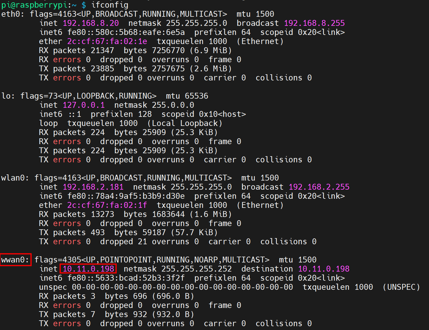
- If the wwan0 interface in the returned information displays a specific IP address, it indicates that the 4G network is connected.
- If the wwan0 interface in the returned information does not display a specific IP address, it indicates that the 4G network is not connected.
- Execute the following command to query the status of the 4G service.
sudo systemctl status ed-lte-daemon.service
The returned information is as shown in the figure below:
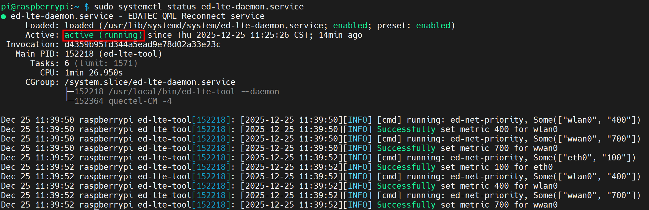
- If the information at the marked position in the returned message shows "Active: active (running)", it indicates that the 4G status is normal.
- If the information at the marked position in the returned message shows "Active: inactive (dead)", it indicates that the 4G status is abnormal.
5.7.2 Scenarios With APN Configuration
If the user's 4G network requires APN configuration, it can be configured by following the steps below.
Preparation:
- The device has started normally.
- A Nano SIM card with 4G network service has been correctly installed into the SIM card slot.
- The APN name, username, and password have been obtained. The following information is used as an example:
- APN name: APN1
- Username: admin
- Password: admin
NOTE
Please turn off the power before inserting or removing the Nano SIM card.
Steps:
- Open the command window and execute the following commands in sequence to open the ed-qml.conf configuration file.
cd /etc/
sudo nano ed-qml.conf
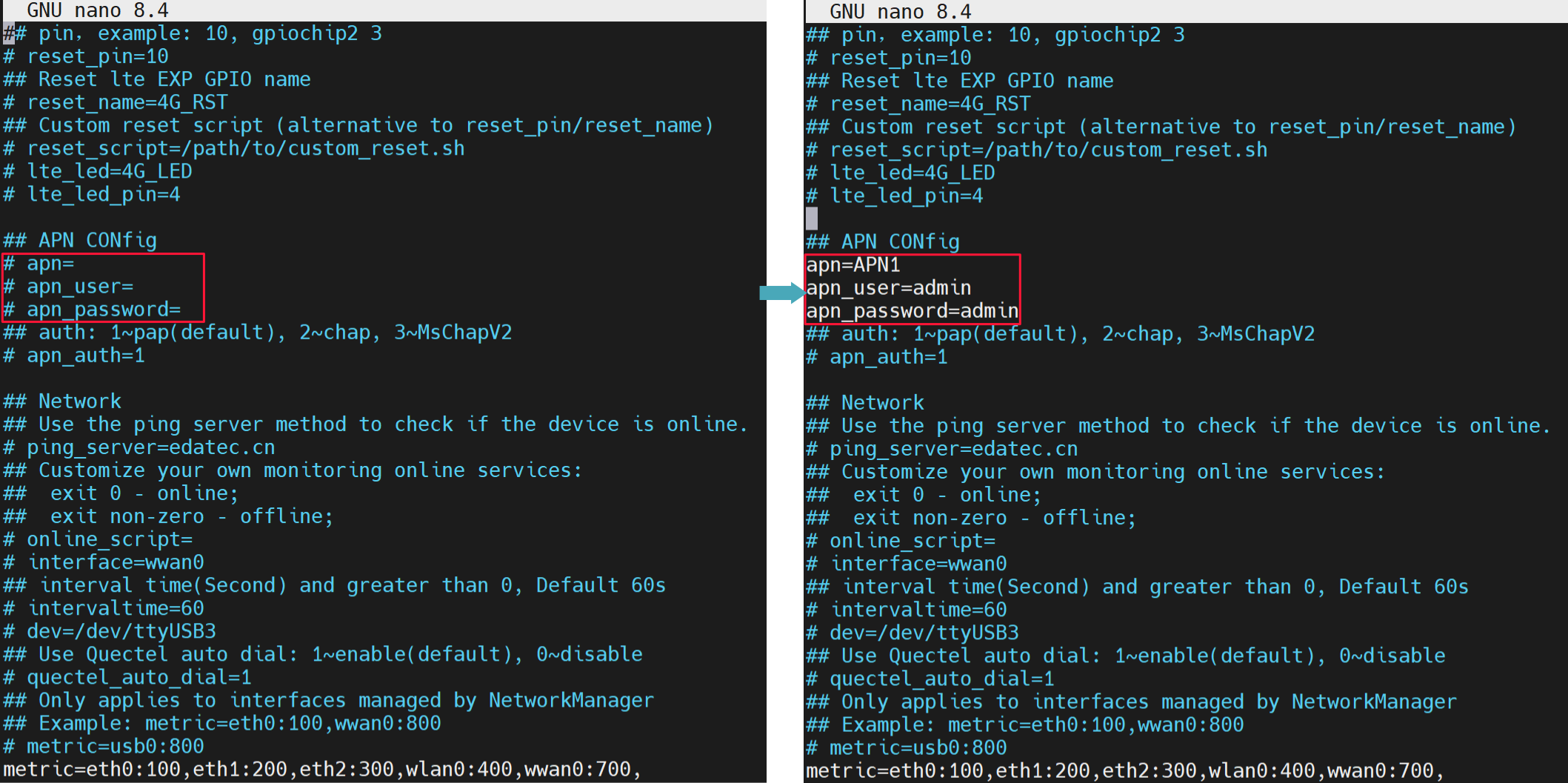
- Configure the "apn", "apn_user", and "apn_password" in the "APN Config" section as needed.
TIP
Parameters such as "4G reset", "Network", and "intervaltime" all support user configuration as needed.
Press
Ctrl+Oto save the file, then pressEnter, and finally pressCtrl+Xto exit the file editing mode.Execute the following command to restart the 4G network service for the configuration to take effect.
sudo systemctl restart ed-lte-daemon.service
- Open the command window and execute the following command to check if the 4G network is connected.
ifconfig
The returned information is as shown in the figure below (the wwan0 interface indicates the 4G interface):
- If the wwan0 interface in the returned information displays a specific IP address, it indicates that the 4G network is connected.
- If the wwan0 interface in the returned information does not display a specific IP address, it indicates that the 4G network is not connected.
- Execute the following command to query the status of the 4G service.
sudo systemctl status ed-lte-daemon.service
The returned information is as shown in the figure below:
- If the information at the marked position in the returned message shows "Active: active (running)", it indicates that the 4G status is normal.
- If the information at the marked position in the returned message shows "Active: inactive (dead)", it indicates that the 4G status is abnormal.
5.7.3 Basic Configuration Commands
If the 4G network cannot be connected, use the following commands for querying and configuration.
| Command | Description |
|---|---|
| sudo ed-lte-tool --daemon | Start the 4G monitoring program and automatically connect to the 4G network |
| ifconfig | Check if the 4G network is connected. The wwan0 interface represents the 4G interface, as shown in the figure below.
|
| sudo systemctl status ed-lte-daemon.service | Check the service status of 4G, as shown in the figure below.
|
| sudo systemctl enable ed-lte-daemon.service | Enable the 4G service |
| sudo systemctl start ed-lte-daemon.service | Start the 4G service |
| sudo systemctl stop ed-lte-daemon.service | Stop the 4G service |
| sudo ed-lte-tool -m | View 4G module information |
| sudo ed-lte-tool -s | Check 4G signal strength |
| sudo ed-lte -c | Dial-up to connect to the internet |
| sudo ed-lte -d | Disconnect the network connection. Automatic reconnection is not supported after disconnection |
| cd /var/log/ed-qmi/ sudo nano xxxx-xx-xx.log | Enter the /var/log/ed-qmi/ directory to view log files, where xxxx-xx-xx is year-month-day, format like 2025-06-18 |
| journalctl -u ed-lte-daemon.service | View real-time logs of the 4G network |
TIP
When the 4G port connection is normal, if the 4G service status is found to be abnormal, you can execute the following commands in sequence to enable and start the 4G service.
sudo systemctl enable ed-lte-daemon.service
sudo systemctl start ed-lte-daemon.service
5.8 Configuring Buzzer
The device contains a buzzer, which supports manually configure the buzzer to turn on and off.
- Execute the following commands to detect and install gpiod tools.
sudo apt update
sudo apt install gpiod
- Execute the following command to turn on and turn off the buzzer.
- Turn on the buzzer:
gpiofind BUZZER_EN | awk '{print substr($0,9)}' | xargs -i bash -c "gpioset {}=1"
1 indicates the high level.
- Turn off the buzzer:
gpiofind BUZZER_EN | awk '{print substr($0,9)}' | xargs -i bash -c "gpioset {}=0"
0 indicates the low level.
5.9 Configuring RTC
The device contains an integrated RTC, which automatically reads the system time synchronously by default, and can manually read and write the system time into RTC.
- Execute the following command to read the RTC time manually.
sudo hwclock -r
- Execute the following command to write the system time into RTC.
sudo hwclock -w
5.10 Configuring Serial Port
This chapter introduces the configuration method of RS232 and RS485.
5.10.1 Installing picocom tool
In the Linux environment, you can use the picocom tool to debug the serial ports RS232 and RS485.
Execute the following command to install the picocom tool.
sudo apt-get install picocom
5.10.2 Configuring RS232
ED-HMI3120-156C includes 2 RS232 ports, and the corresponding COM ports and device files are as follows:
| Number of RS232 Ports | Corresponding COM Port | Corresponding Device File |
|---|---|---|
| 2 | COM1, COM3 | /dev/com1, /dev/com3 |
Preparation:
The RS232 port of ED-HMI3120-185C has been connected with external device.
Steps:
- Execute the following command to open the serial port com1, and configure the serial port baud rate to 115200.
picocom -b 115200 /dev/com1
- Input commands as needed to control external device.
5.10.3 Configuring RS485
ED-HMI3120-185C includes 2 RS485 ports, and the corresponding COM ports and device files are as follows:
| Number of RS485 Ports | Corresponding COM Port | Corresponding Device File |
|---|---|---|
| 2 | COM2, COM4 | /dev/com2, /dev/com4 |
Preparation:
The RS485 port of ED-HMI3120-185C has been connected with external devices.
Steps:
- Execute the following command to open the serial port com4, and configure the serial port baud rate to 115200.
picocom -b 115200 /dev/com4
5.11 Configuring Audio
The device contains one audio (supports access to MIC) and one extended speaker output. The volume of Master, MIC and Speaker can be adjusted, and support recording for MIC.
5.11.1 Adjust The Volume
It supports manual adjustment of MIC, Speaker and Master volume.
- If you are using the Desktop version of the operation system, you can adjust the volume of the MIC and Master directly through the desktop icon.
Steps:
- Click the icon
 or
or in the upper right corner of the desktop to open the volume adjustment column.

- Drag the button of the volume adjustment column up and down to adjust the volume, check or uncheck the Mute check box to mute and unmute the audio.
- Both Desktop and Lite versions of the operation system support opening the volume adjustment interface through the command line to adjust the volume.
Steps:
- Execute the following command to open the volume adjustment interface.
alsamixer
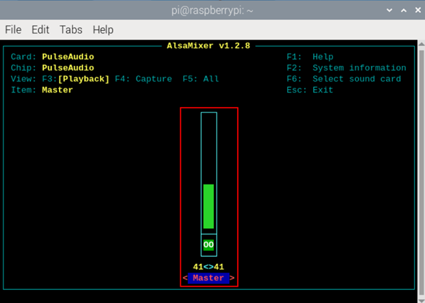
- View the volume value of the current Master in the opened interface. You can adjust the volume through the ↑ key and ↓ key on the keyboard, and press the M key to mute and unmute the audio.
| Keyboard Key | Function |
|---|---|
| ↑ | Volume+ |
| ↓ | Volume- |
| M | Mute or Unmute |
- Press F6 to open "Sound Card" interface, select "1 USB Advanced Audio Device".
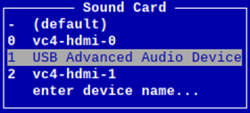
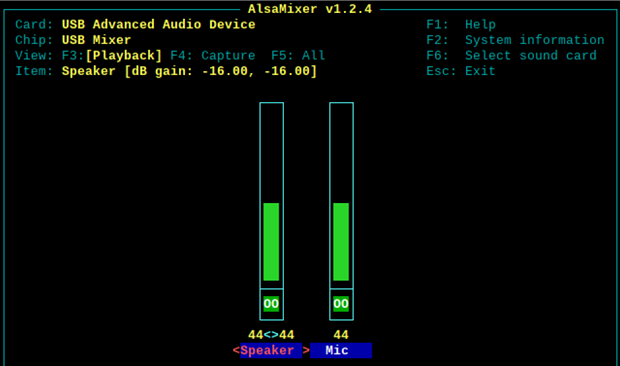
- Press Enter to open the volume interface of MIC and Speaker, and you can adjust the volume of MIC and Speaker respectively throughthe ↑ key and ↓ key on the keyboard, and press M to mute and unmute MIC/Speaker.
| Keyboard Key | Function |
|---|---|
| ↑ | Volume+ |
| ↓ | Volume- |
| M | Mute or Unmute |
5.11.2 Configure Recording
It supports the audio recording of MIC input.
Preparation:
The audio interface has been connected to MIC.
Steps:
- Execute the following command to open the volume adjustment interface.
alsamixer
- Press F6 to open the "Sound Card" interface, select "1 USB Advanced Audio Device", and press Enter to open the volume adjustment interface of MIC and Speaker to ensure that MIC is not muted.
- Press Esc to exit to the command pane, execute the following command to query the number of the sound card device representing the recording.

- After obtaining the number, execute the following command to start recording audio named audio1, as shown in the figure below.
arecord -fcd -Dhw:1 -c 1 --vumeter=mono audio1

| Parameters | Description |
|---|---|
| cd | Indicates the audio format, which can be set to cd, cdr, dat and other formats, and can be set as needed. |
| audio1 | Indicates the recorded file name, which can be customized by the user. |
Use Ctrl+C to close recording.
Execute the following command to obtain the storage path of the recording file.
pwd

- In the directory where the recording file is located, execute the following command to play the audio.
aplay audio1

5.12 Configuring USER Indicator
The device contains a USER indicator, and users can customize the status according to actual needs.
- Execute the following commands to detect and install gpiod tools.
sudo apt update
sudo apt install gpiod
- Execute the following command to turn on and turn off the USER indicator.
- Turn on the USER indicator:
gpiofind USER_LED | awk '{print substr($0,9)}' | xargs -i bash -c "gpioset {}=0"
0 indicates the high level.
- Turn off the USER indicator:
gpiofind USER_LED | awk '{print substr($0,9)}' | xargs -i bash -c "gpioset {}=1"
1 indicates the low level.